Developement of 3D printing device for the production of atypical structure
Introduction
With the recent development of CAD/CAM technology, the number of atypical building projects is increasing. However, atypical construction project is difficult to apply with the existing construction method, and the cost of the construction increases. To minimize this, a new construction method, S-LOM (Sloped Laminated Object Manufacturing) method was proposed by improving the quality of molds by stacking EPS (Expanded Poly-Styrene) boards. The S-LOM method is a technique that reduces the error of the shape by applying the slope to the cutting surface. Five-axis laser cutting machine was used to cut EPS boards. In this research, through checking the building time of freeform bench and freeform surfaces of manufactured bench, we checked possibility of S-LOM technique application to architecture.
Research Territories
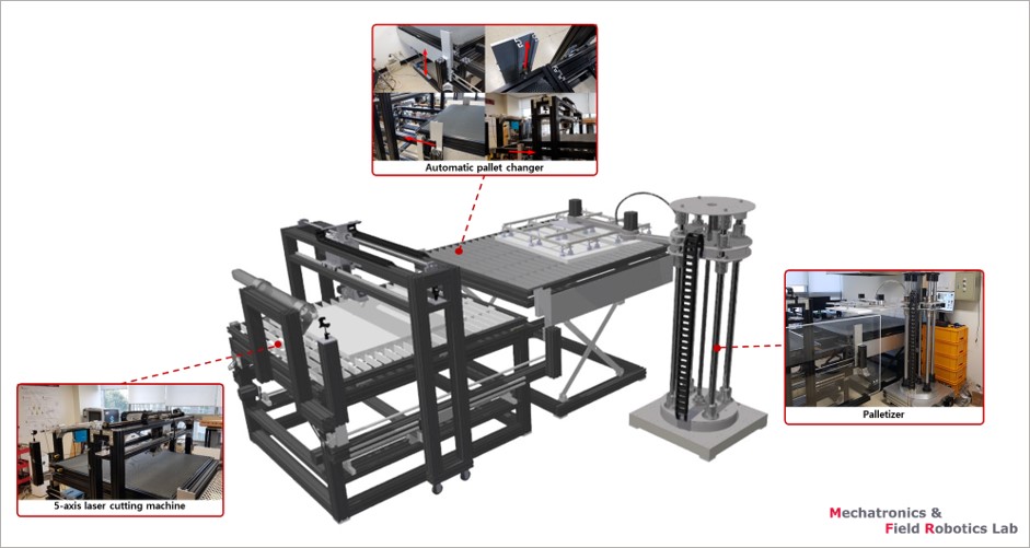
(1) Laser Cutting Machine
Laser cutting equipment was developed based on a five-axis coordinate system to implement inclined cutting. The laser cutting device consisted of three straight axis of motion (X, Y, Z axis) and two additional axes of rotation (B and C axis) for the Y and Z axes. In this equipment, a head-head format useful for large-scale machining was selected, and rapid processing and wide workspace are provided. The movement of the laser head moves on the gantry structure, and the laser source of the equipment was selected for 75W CO2 laser through EPS cutting base experiment. The X, Y, and Z axes, which move in a straight line, and the B and C axes that rotate, are equipped with reflectors that bend the laser beam. It refracts a laser beam that has been triggered from a laser source and leads it to the surface of the workpiece. CO2 laser cutting is cut by applying high energy to a specific location of the material by concentrating the laser beam on a single point through the convex lens.
(2) Cutting path generation algorithm
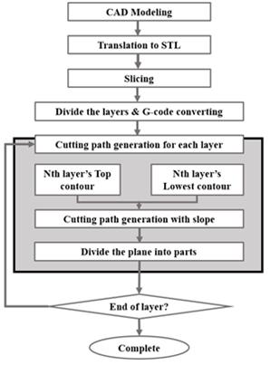
We proposed an algorithm that can generate a form cut path to create a target model with F3D printer. Fig. 2 shows the cutting path algorithm in a simple diagram. First, a 3D CAD drawing is generated for the production model, and the 3D CAD drawing is converted into an STL type file. The STL file is sliced in consideration of the thickness of the styrofoam board to be used and the shape of the model. A cutting path is created for the sliced layer. Divide the generated cutting path into sizes that can be manufactured considering the working space, and divide the entire cutting path so as to generate the mold cut pieces. After cutting the styrofoam board by using the cutting path thus created, the unit mold is laminated by bonding, and the unit mold is bonded and assembled to form an entire mold.
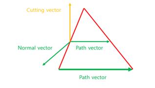
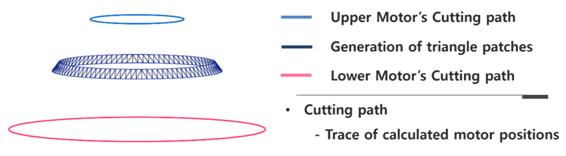
Creates paths for the top and bottom motors from the generated triangle shape. The upper and lower perimeters have point information, which is followed by a side triangle. From this information, a triangular shape was created on the side by the Delaunay triangle method. At this time, the normal vector perpendicular to the plane and the path vector tangent to the movement path can be obtained from each triangle shape. That is, the normal vector is the direction perpendicular to the plane with respect to the triangular shape, and the path vector is the tangential direction along the cutting direction. The normal vector can be defined for all triangular shapes, and is the direction perpendicular to or out of each triangular shape. These two directions can be obtained by designating two sides as a vector in a triangle shape, and an external surface cutoff vector irrespective of the order. Fig. 3 shows the cut vector obtained by using the normal vector and the path vector.
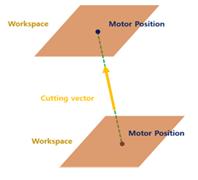
The path vector can be obtained as follows. Among three sides of a triangle shape, one point is on the upper circumference, the other is the bisector of the sides on the lower circumference, and the middle circumference is obtained by dividing the bisector obtained from all the triangle shapes. The path vector can also be defined for all triangles and can be defined as a vector of two triangles that form an intermediate perimeter. In this way, we can define the path vector and the normal vector, and obtain the position vector of the motor parallel to the triangle shape and perpendicular to the path vector externally. For all triangular shapes, determine the points to be the reference in the triangular shape. When the middle circumference is turned counterclockwise, the intersection of the triangle shape and the first intersection is set as the reference point. At this point, the intersection of the extension line of the motor position vector and the plane corresponding to the height of the upper and lower motors is obtained. Fig. 4 is a schematic diagram in which an extension line of a cut-off vector is obtained by calculating an intersection point with a workspace. At this time, the two points are the position of the upper motor and the position of the lower motor, respectively, and the cutting path can be obtained by sequentially following the set of these points. Fig. 5 is the simulation result of the cutting path created by connecting the motor positions in order.

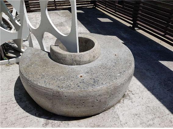
F3D프린터 출력 결과물(비정형 벤치)