Construction Automation of High-rise building based on robotic crane (2006~2011)
Motivation
Automated construction using robotic technologies is the focus of this project.
The key issues addressed by this research consist of the following four technologies:
(1) Construction automation system planning and integration for robotic crane based high-rise building structure,
(2) Climbing hydraulic robot and CF structure technology,
(3) Robotic crane based construction material installation technology, and
(4) RFID (Radio Frequency Identification) and multi-DOF CAD based intelligent construction material supply system.
Among the four categories listed above, we focus on "(3) Robotic crane based construction material installation technology". In order to perform the task (3), an automation system for robotic beam assembly is necessary. Developing the automation system, we can expect following effects: saving construction period and cost, enhancing operator's safety by replacing human workforce with robotic systems, and improving overall quality. Fig. 1 shows the schematic view of the construction automation system planned in Korea.

Fig.1 Schematic Diagram of Construction Automation of High-Rise Building Based on Robotic Crane
Research Territories
(1)Robotic Bolting Device
Development of Bolting Robotic manipulator
Robotic manipulator has the purpose of placing the bolting end-effector to a target position to join a pair of beams and/or column. At the end of the z-directional frame, the bolting end-effector is attached. The robotic manipulator has a gantry-type mechanism which can generate 3-DOF motion with three motors and linear guides. The three frames of the manipulation system are exactly matched to three dimensional Cartesian coordinates, so that it can be easily controlled with a simple control algorithm.

Fig.2 Bolting Robotic Manipulator Configuration
Design of Bolting End-Effector
The bolting end-effector composes of bolt feeding device, bolting device and rotary table. A gripper on the bolting end-effector holds the bolt feeding device, and bolting robotic manipulator transfers the bolt feeding device to target positions on H-beam. After reaching the target points, the bolt feeding device attaches to the H-beam using magnetic base. The bolt feeding device inserts the bolts to the holes using elastic force of the spring. Also the bolt feeding device attached to H-beam using magnetic force prevents the bolts from detaching down. The bolting device actually performs bolting task. In the bolting task, TS (Torque Shear) type bolt is utilized which has a pintail and a break neck at the end of the bolt. If bolting torque approaches to a designated value, the break neck is cut and the pintail is detached off from the bolt body. It is actuated with an air-motor and a gear box to generate torque enough to fully assemble a bolt and nut pair.
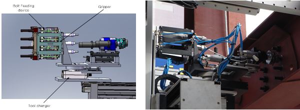
Fig.3 Bolting End-Effector Configuration
(2)Robotic Mobile Mechanism
In order to implement the robotic automation system for steel beam assembly, a mobile mechanism to transport the robotic bolting device to a target position is required. In this research, we developed a rail sliding boom mechanism and a scissors-jack type mobile manipulator.
Rail Sliding Boom Mechanism
Fig. 4 shows the rail sliding boom mechanism. This mechanism consists of a boom part and driving parts. Since the boom part has the function of variable length, it is able to turn around the corner, where the distance between the inside rail and the outside rail is larger than the straight section. Two driving parts are located at both ends of the boom body, and slide on the rail structure placed on the CF to transport the mobile mechanism and the robotic bolting device. Also, they are connected to the boom body with passive hinges and can be independently controlled to increase the mobility specially on the corner driving.
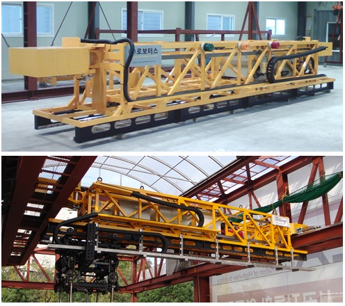
Fig.4 Rail sliding boom mechanism
Wire type Mobile Mechanism
The wire type mobile manipulator is suspended from the linear guide attached on the boom body. Along the linear guide, it can slide horizontally adding 1 DOF to the rail sliding motion of the boom mechanism. Since the basic function of this mechanism is to make z-directional motion, considering the rail sliding boom mechanism and the wire type mobile manipulator at the same time, the whole robotic mechanism makes a complete spatial motion. Moreover, the cabin is linked to the other end of the wire mechanism with a rotational joint enabling an additional angular motion and improving its reachability to the target positions. The motion of the rail sliding boom mechanism and the wire type mobile manipulator can be independently controlled and the successful mobile operation of the whole robotic mobile mechanism was achieved by experiments.
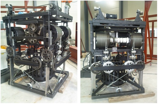
Fig.5 wire type mobile manipulator
(3) Bolting Control System
The bolting control system aims to efficiently and safely operate the robotic automation system for steel beam assembly making the use of sensor network, user interface, and intelligent software technologies. The control system includes following technologies: hole recognition system based on vision sensing, ITA (Intelligent Teaching Agent) system to provide the operator with an efficient instruction and prevent unexpected accidents during operation, and haptic based HMI (Human Machine Interface) system to confirm the reliability of bolting operation.
Hole Recognition Based on Vision Technology
The hole recognition system recognizes visual information collected from vision sensors and provides the operator or the controller with position information of the holes and bolts. This system has two cameras as vision sensors. The wide angle camera gives overall environment information for the robotic bolting device to move to the target bolting position. And the small camera attached on the bolting robot arm obtains precision position information for holes and bolts recognition. With this information, this recognition system performs image processing and transfers it to the control system.
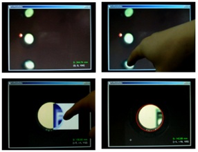
Fig.6 Image Capture of Hole Recognition Based on Visual Servoing
ITA (Intelligent Teaching Agent) System
ITA system suggested in this research consists of two main parts. The first part has the function of showing environmental information. It collects the information gathered by the sensors and helps the operator to realize the operational environment and react to dangerous factors which may cause unexpected incidents. The second part gives the operator operation status to guide the next step according to the optimal working procedure so that the operation time can decrease. This system uses a wide angle camera to visualize spatial workspace. And it overlays three steps of guidelines over the monitor to provide the operator with visual and alarm information corresponding to three steps of precaution level: robot operation area, precaution limit area, and precaution free area.
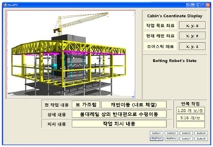
Fig.7 ITA System Configuration
Integration of Robotic Beam Assembly System
System integration takes a role of combining the entire systems including the robotic bolting device, the robotic mobile mechanism, and the bolting control system. In this study, the system integration is homed in the control station which is placed on the cabin. Inside the cabin, the operator remotely controls the robotic systems, manages the whole automation process, and performs troubleshooting when the system malfunctions. With the monitoring device equipped in the control station, the user interface contains following features:
- States of the robot including the current operation, position information of each device, alarms, and etc.
- Sensory information from sensor network including camera image.
- Automatic manipulation and bolting function.
Table represents the basic procedure for bolting operation. Iterating the procedure, the whole beam assembly of a building can be completed.
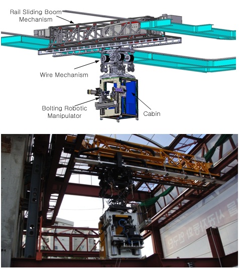
Fig.8 Integration of robotic automation system for steel beam assembly
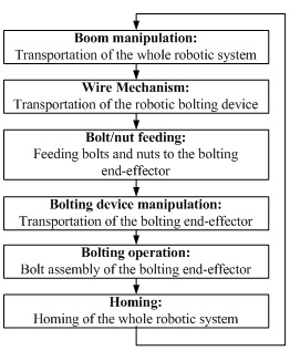
Table.1 Overall Beam Assembly Procedure by Bolting Operation
Sponsor
This research was supported by a grant (code# 06-D01) from Unified and Advanced Construction Technology Program funded by Ministry of Construction & Transportation of Korean government